Can someone explain to me why one circuit diagram variant has more contacts?
Hello,
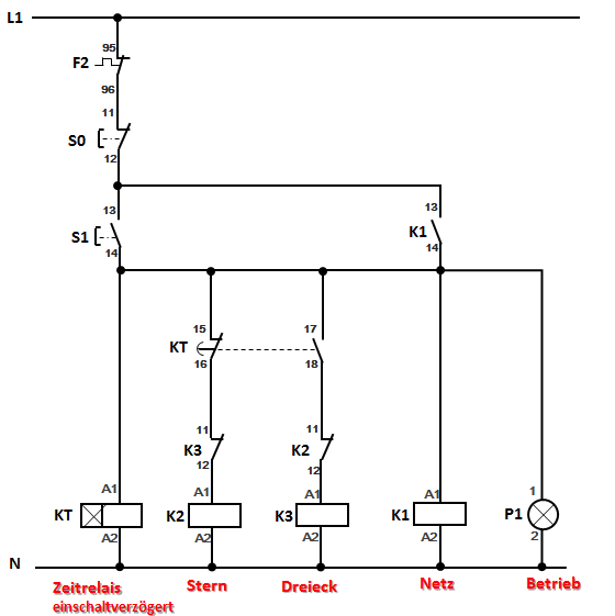
These two controllers are automatic star-delta circuits. As far as I can see, they do exactly the same thing. Why does one version have 7 switching points and the other 5? I don't see any advantages of the "7" controller over the other… (By switching points, I mean all the contacts necessary for controlling the motor, not signal lights.)
Regarding the plan with 7:
Q1 = mains contactor
Q2 = star
Q3 = triangle

Thanks
You need to be a registered member to rate this.
The first drawing comes with buttons, the second with switches when I correctly interpret the switching characters.
The advantage of the lower circuit is that the mains contactor Q1 must already be attracted so that the time relay K1T can attract. This is not the case in the upper part, because the time relay already attracts when operating S1. That is, the lower circuit is somewhat more elegant with regard to switching transition.
In the second plan, you have a consumer.
There's only one consumer. It's 1 engine. The indicator lights don't matter…OR what do you mean?